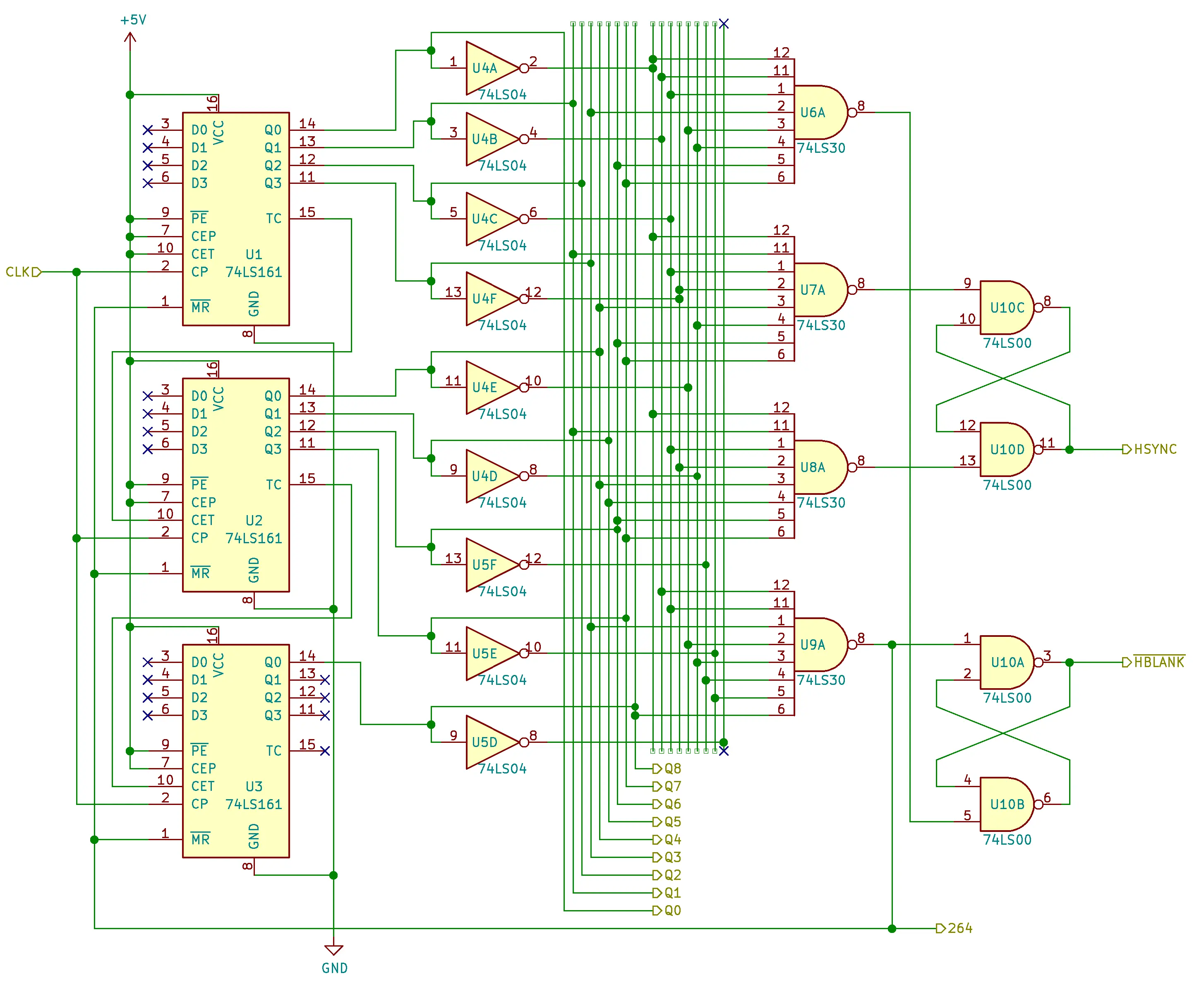
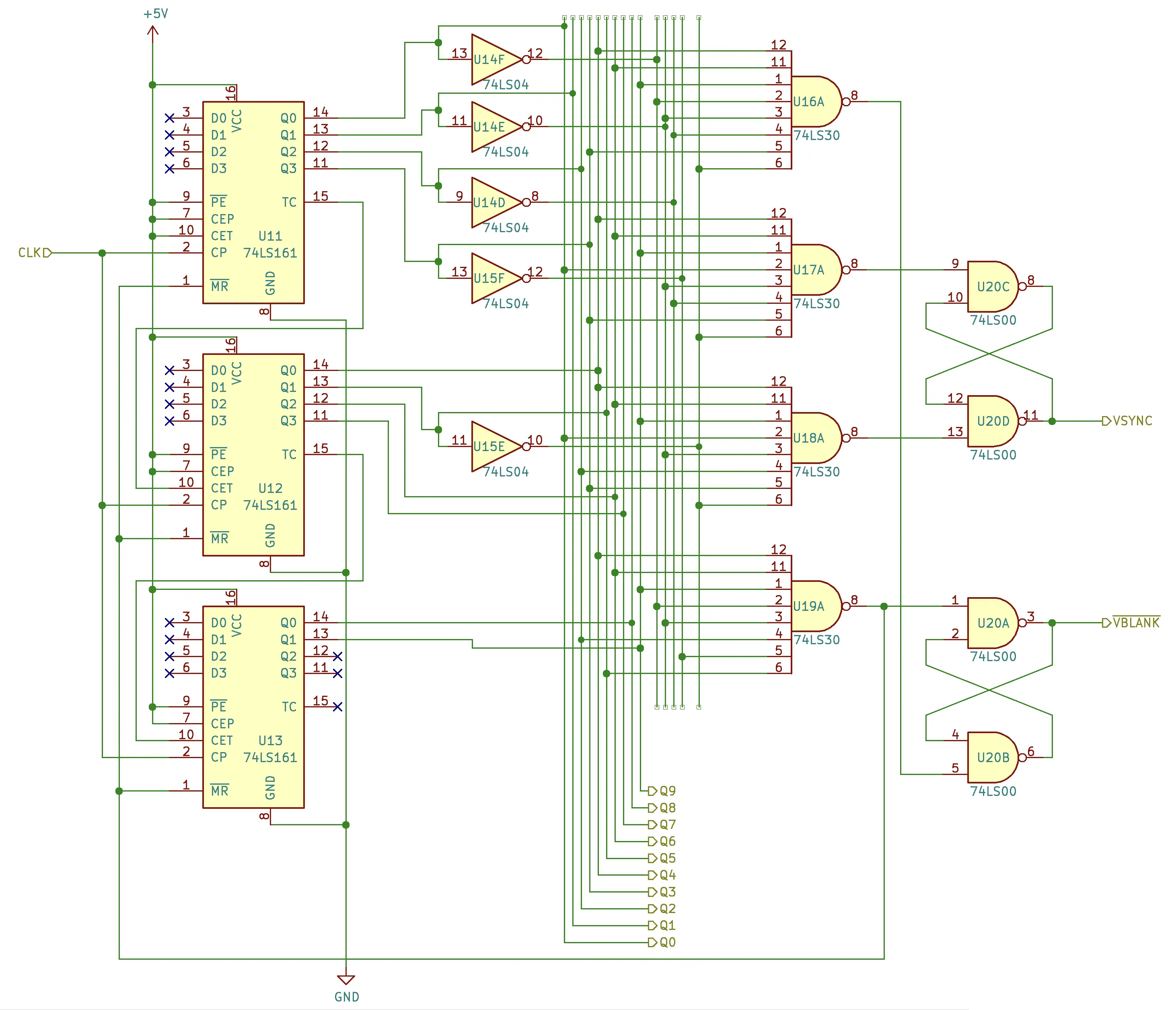
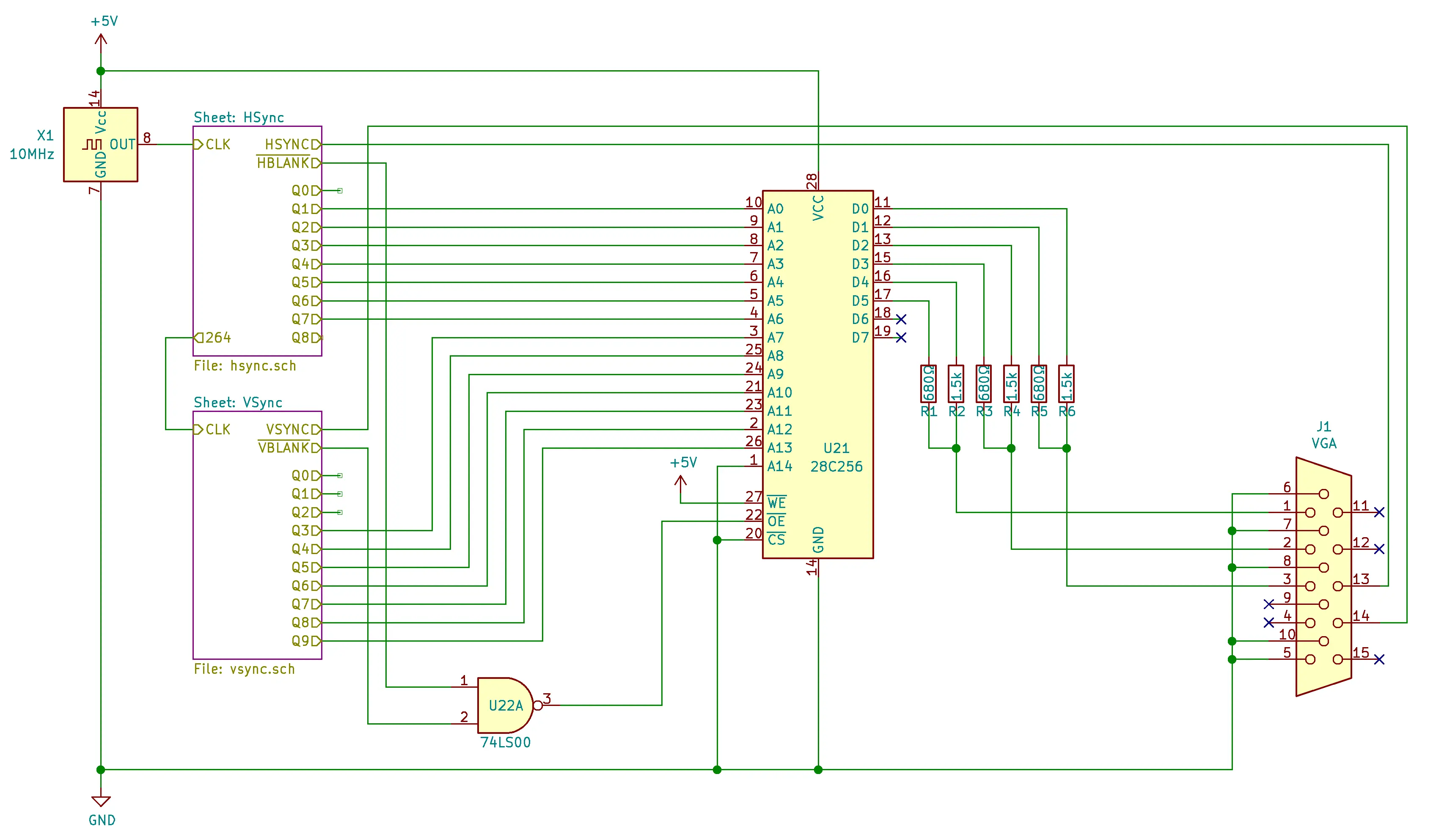
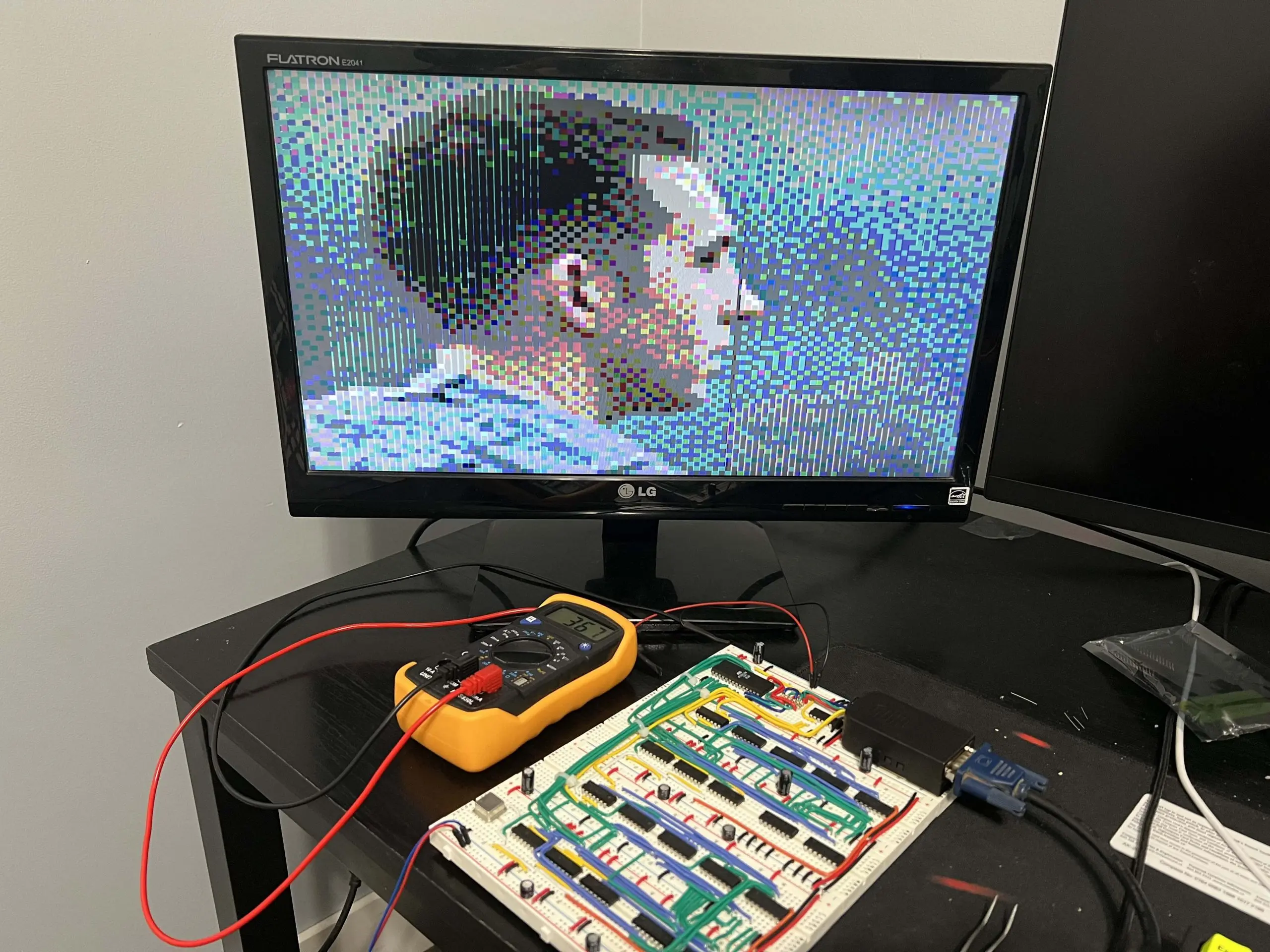
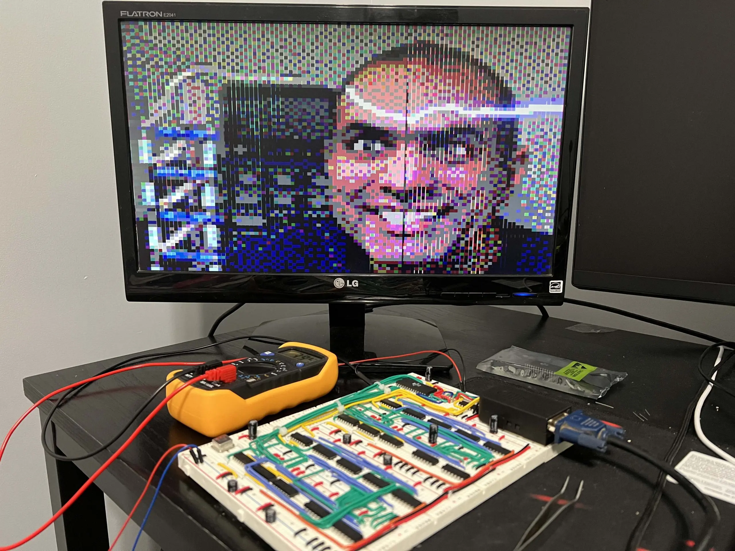
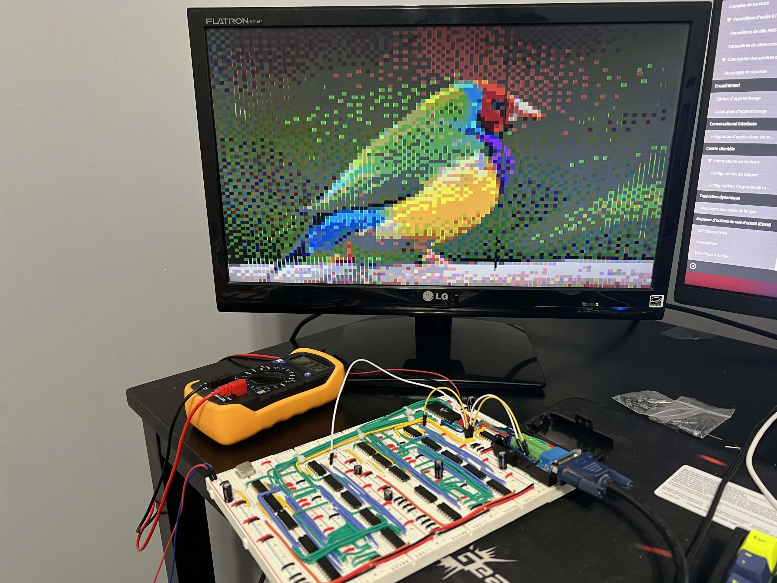
This is my second Ben Eater project. In this video series, Ben talks about how VGA signals work and walks us through building a circuit that provides the correct timing of sync signals so that a monitor recognizes the signal and displays an image stored on an EEPROM.
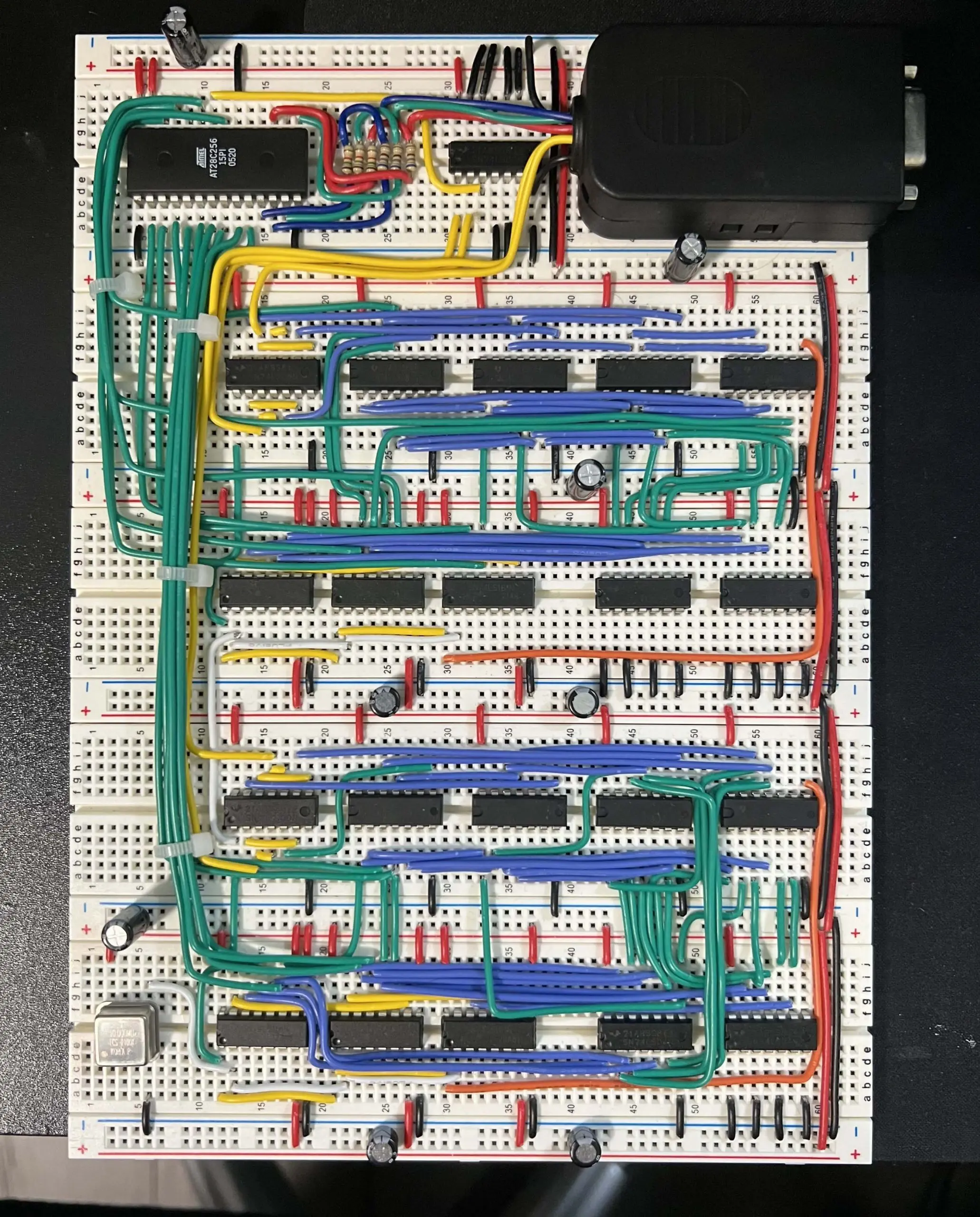
This video card displays an image of 100 x 75 pixels with 64 (indexed) colors.
BOM (Electrical)
| Description | Quantity |
|---|---|
| Breadboard | 5 |
| 22 AWG Solid Tinned-Copper Hook-Up Wire | 1 |
| 10MHz full can crystal oscillator | 1 |
| 680Ω resistor | 3 |
| 1.5kΩ resistor | 3 |
| 74LS00 (Quad NAND gate) | 3 |
| 74LS04 (Hex inverter) | 4 |
| 74LS30 (8-input NAND gate) | 8 |
| 74LS161 (4-bit synchronous binary counter) | 6 |
| 28C256-15 EEPROM | 1 |
| DE15 Female VGA breakout connector | 1 |
You will also need a monitor with VGA input, an EEPROM programmer like the XGecu TL866II Plus, an oscilloscope and a function generator.
Schematics