Arduino Nano based program loader for 8bit CPU

As you might know from a previous post, I built Ben Eater’s 8bit TTL CPU on breadboards in the past. The CPU is fully programmable with 16 bytes of memory and 11 Op Codes that can be used to write programs, one instruction per byte. This programming has to be done manually using DIP switches every time the device is powered on. It is a bit tedious as you have to enter instructions in binary for each memory location by hand. I have been learning PCB design and would like to convert this project to a PCB build in the near future. One of the things I would like to add is a program loader that can automatically load programs into the memory on boot. Before implementing this on a PCB, I wanted to have a working prototype that connects with my Breadboard CPU.
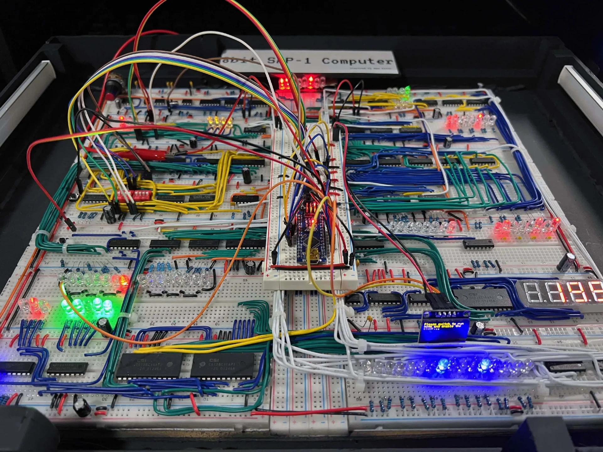
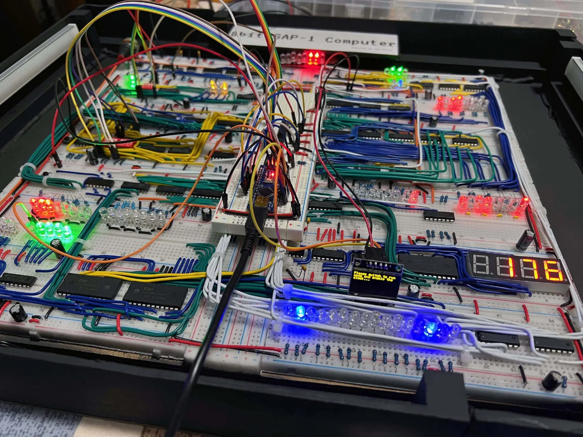
Pin Mapping
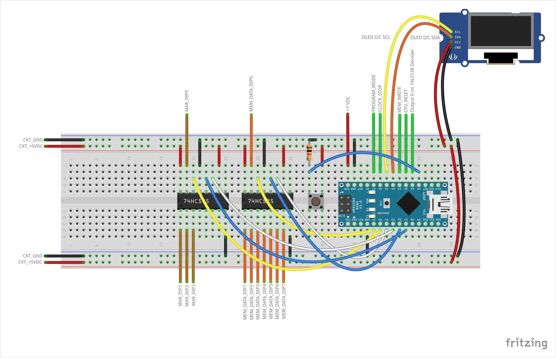
Arduino
- D2 to Shift Register 1 Pin 14
- D3 to Shift Register 2 Pin 14
- D4 to Shift Register 1 Pin 12
- D5 to Shift Register 2 Pin 12
- D6 to Shift Register 1 Pin 11
- D7 to Shift Register 2 Pin 11
- A0 to Push Button input with 10K pull-down resistor
- A1 to Output 0 on 74LS138 Decoder
- A2 to CPU_RESET
- A3 to MEM_RESET
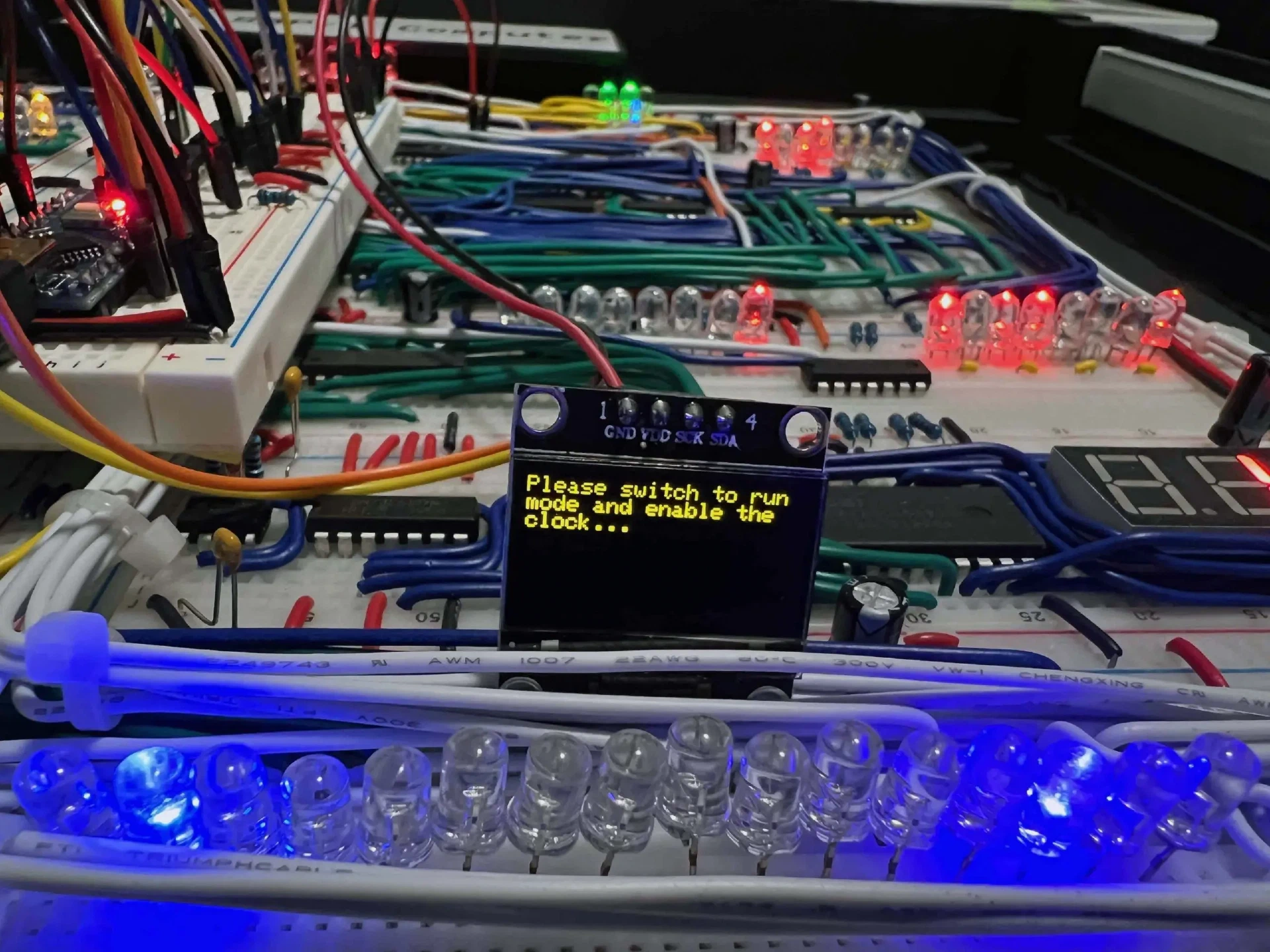
- A4 to OLED I2C SDA
- A5 to OLED I2C SCL
- A6 to the clock enable/disable button
- A7 to the programming/run mode button
Shift Register 1
- Pin 15 to Data DIP0 switch
- Pin 1 to Data DIP1 switch
- Pin 2 to Data DIP2 switch
- Pin 3 to Data DIP3 switch
- Pin 4 to Data DIP4 switch
- Pin 5 to Data DIP5 switch
- Pin 6 to Data DIP6 switch
- Pin 7 to Data DIP7 switch
Shift Register 2
- Pin 15 to Address DIP0 switch
- Pin 1 to Address DIP1 switch
- Pin 2 to Address DIP2 switch
- Pin 3 to Address DIP3 switch
Notes
- Vin pin on the Arduino can optionally be connected to a +7-12 VDC input.
- Please ensure Vin and USB are not both connected at the same time.
You can find the most up-to-date code on my GitHub Repo. I use a 3rd party platform called PlatformIO for writing Arduino programs in VS Code. But you can simply copy the code from src/main.cpp and run that in the Arduino IDE.
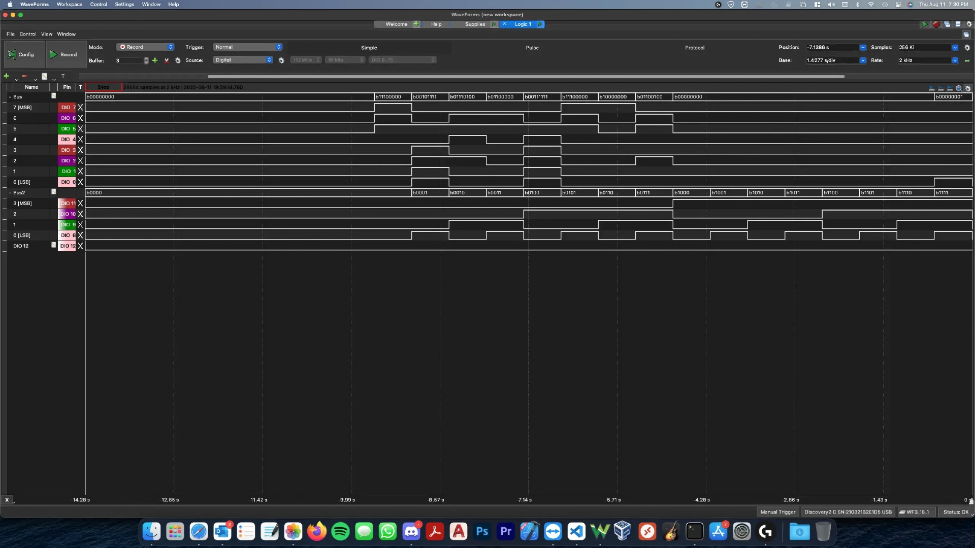
The data to be programmed to the memory is stored in a byte array named code (in decimal format). 16 values are programmed in 16 memory locations, each value is converted to binary in their respective function call. The below code adds a number (saved in memory location 15 i.e. 1111) repeatedly to itself until the upper limit (255) is reached, it then repeatedly subtracts that value from itself until it reaches 0, and it keeps looping.
byte code[] = {224, 47, 116, 96, 63, 224, 128, 100, 0, 0, 0, 0, 0, 0, 0, 1};
| Memory location | Array value | Binary value | Op Codes |
|---|---|---|---|
| 00 (0000) | 224 | 1110 0000 | OUT |
| 01 (0001) | 47 | 0010 1111 | ADD 15 |
| 02 (0010) | 116 | 0111 0100 | JC 4 |
| 03 (0011) | 96 | 0110 0000 | JMP 0 |
| 04 (0100) | 63 | 0011 1111 | SUB 15 |
| 05 (0101) | 224 | 1110 0000 | OUT |
| 06 (0110) | 128 | 1000 0000 | JZ 0 |
| 07 (0111) | 100 | 0110 0100 | JMP 4 |
| 08 (1000) | |||
| 09 (1001) | |||
| 10 (1010) | |||
| 11 (1011) | |||
| 12 (1100) | |||
| 13 (1101) | |||
| 14 (1110) | |||
| 15 (1111) | 1 | XXXX 0001 |