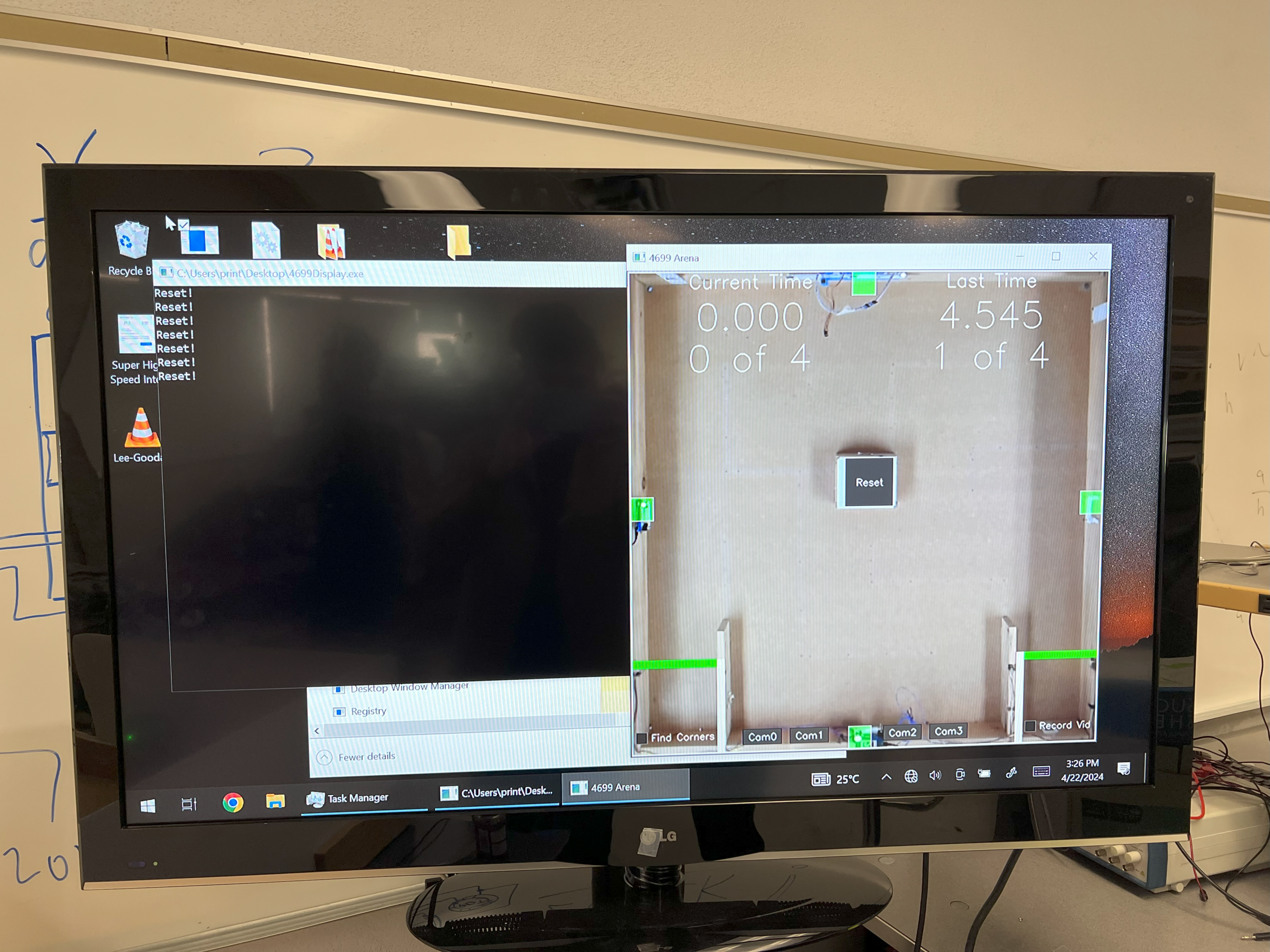
In the BEng EE program at BCIT we have two 4-week summer terms. One of them is taken right after the first year and the second one can be taken after the completion of the second or third year. I recently completed that second 4-week term, and one of the courses I took was ELEX 4699 – Electronics System Design Project. The goal was to create a robot rover that navigates an arena, and shoots targets while minimizing completion time. The arena, functioning as a server, sends data to connected client robots. Clients use a Raspberry Pi as the host controller, and a PiCam with OpenCV for image recognition.
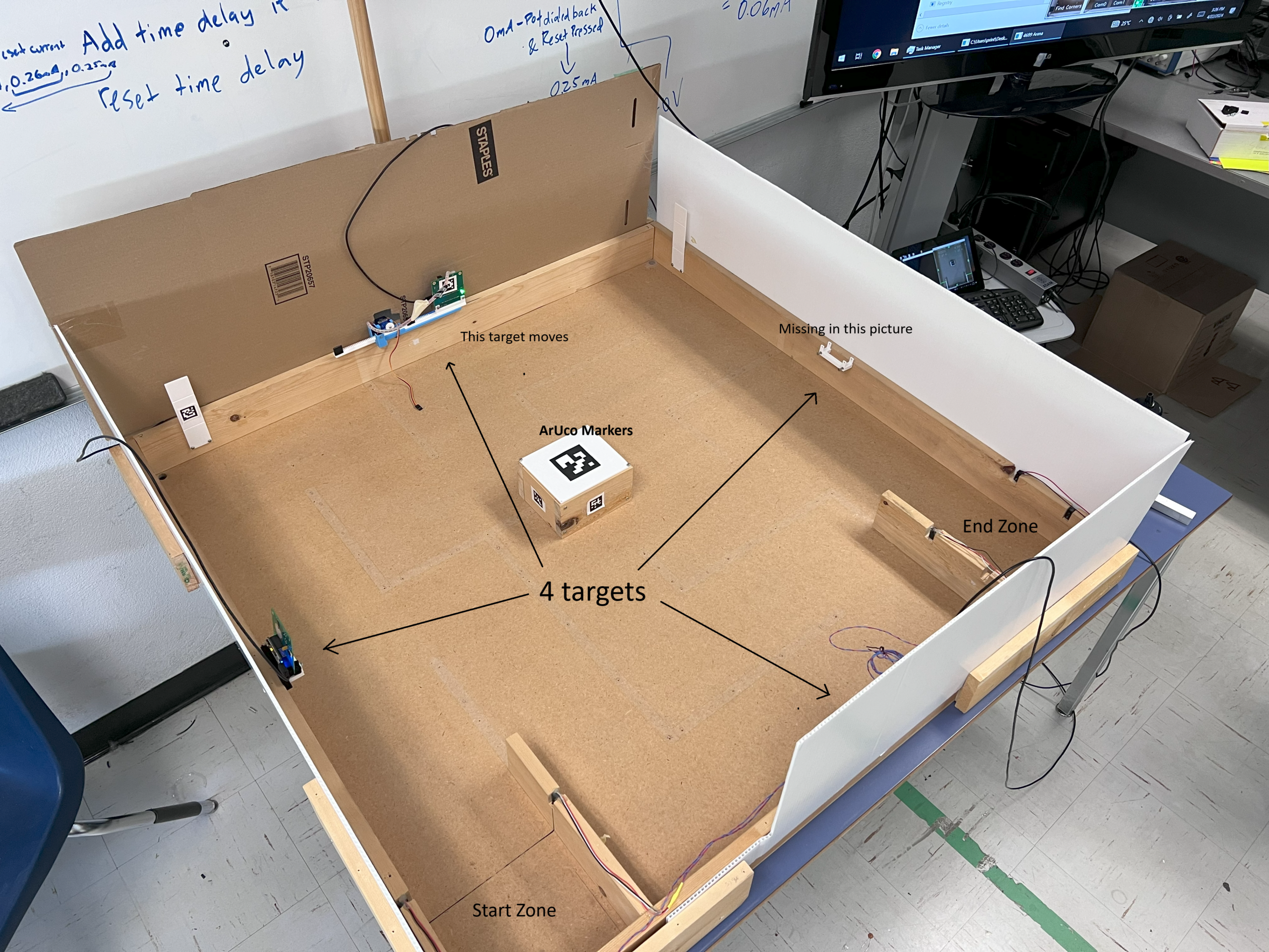
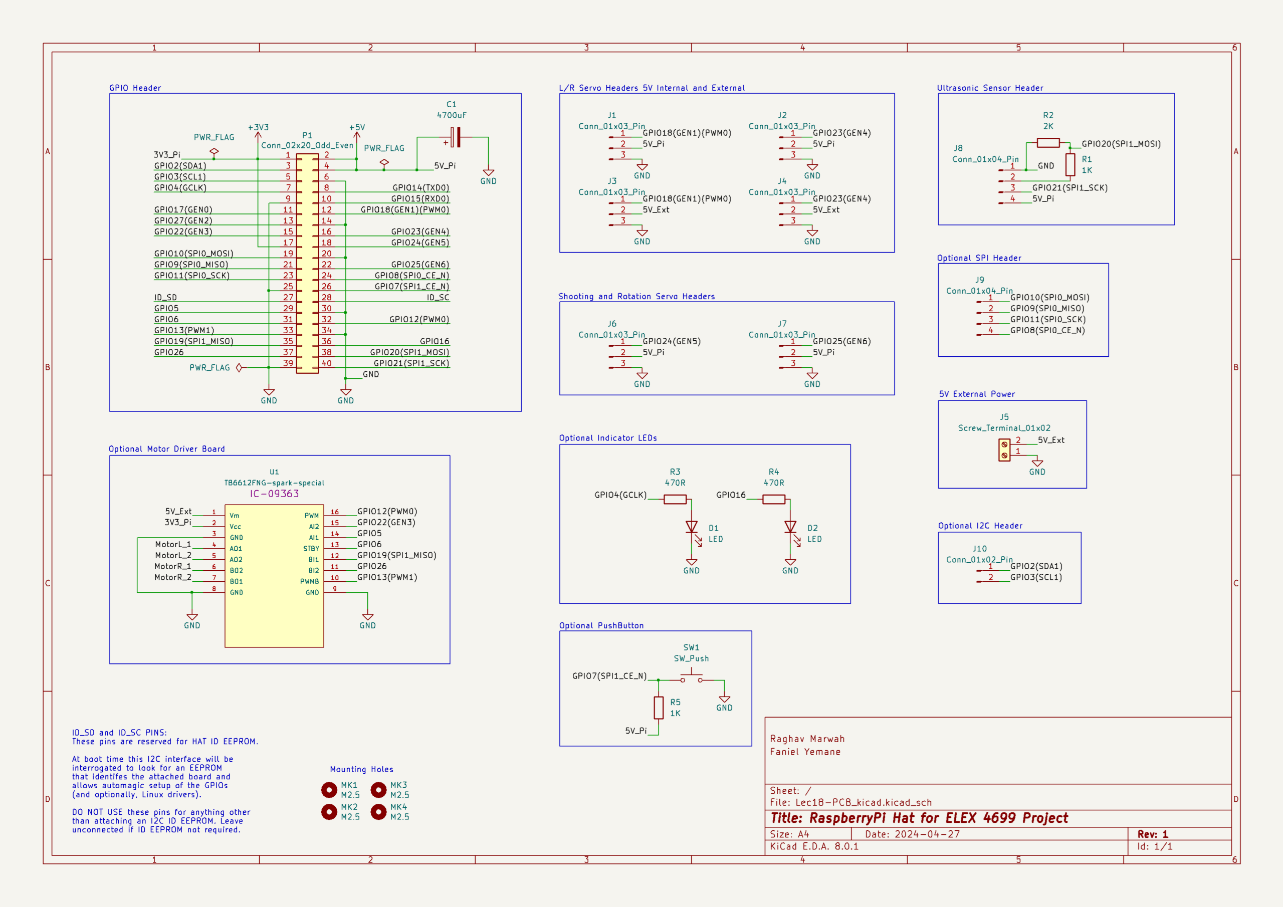
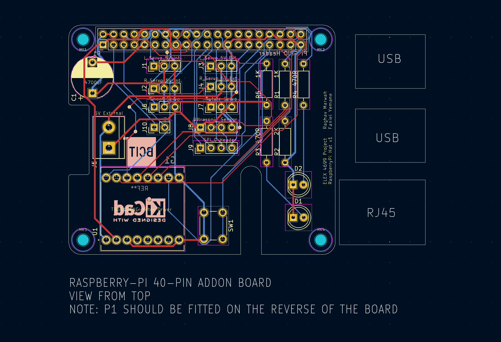
My teammate for this project was Faniel Yemane, so a big shoutout to him for collaborating on and contributing to this project. Teams were marked based on the time taken to complete the autonomous and teleoperations run (40% each) and two early milestones completed during the first two weeks (10% each). One of the requirements of the project was to design and use a PCB that connects to the Pi GPIO pins (a Pi Hat) and allows other hardware and sensors to connect easily. This was an optional requirement, but teams with a PCB got a time bonus.
I used two MG995 servos for the left and right motors and an SG90 servo for the shooter. I modified these servos to spin 360° by following the instructions here. The ultrasonic sensor is HC-SR04 which works with a 5V logic level, to make it work with the Pi we need to install a voltage divider as described here. I used Fusion 360 to design all the parts and they were 3D printed with PLA.
The robot operates in two modes:
- Manual mode: The car is driven by a human driver via a TCP/IP connection.
- Autonomous mode: The robot functions independently without human intervention.
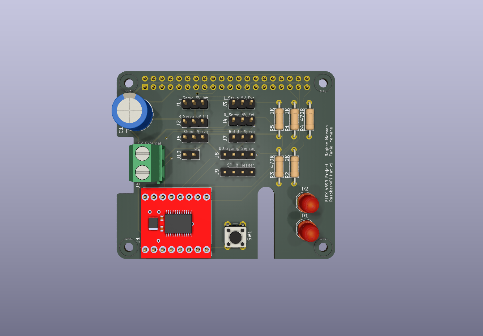
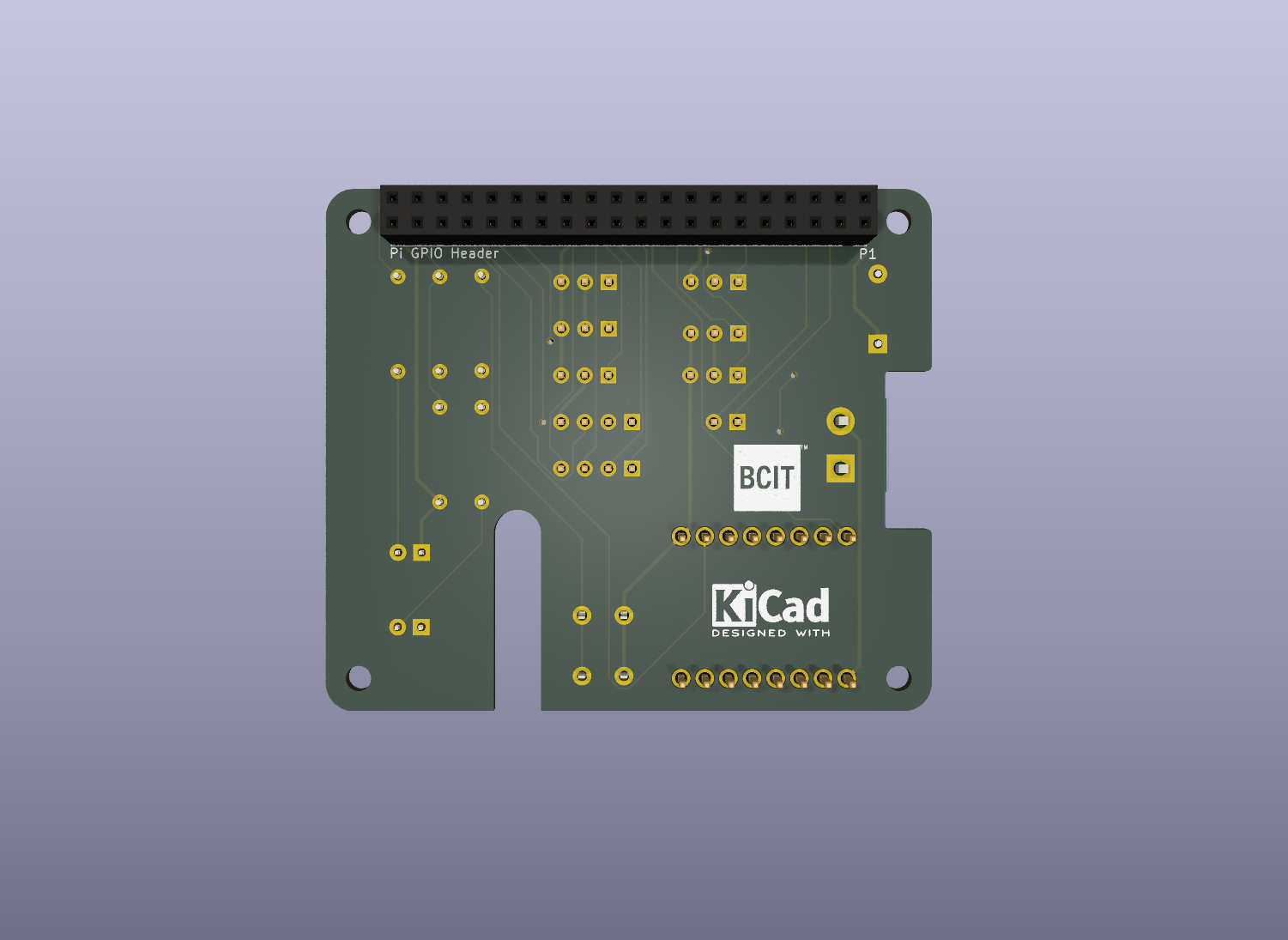
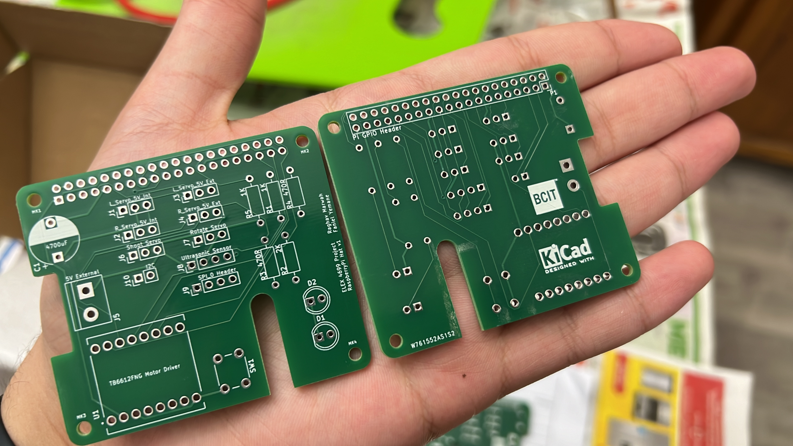
PCB Schematic, PCB Layout, 3D render, and actual PCBs
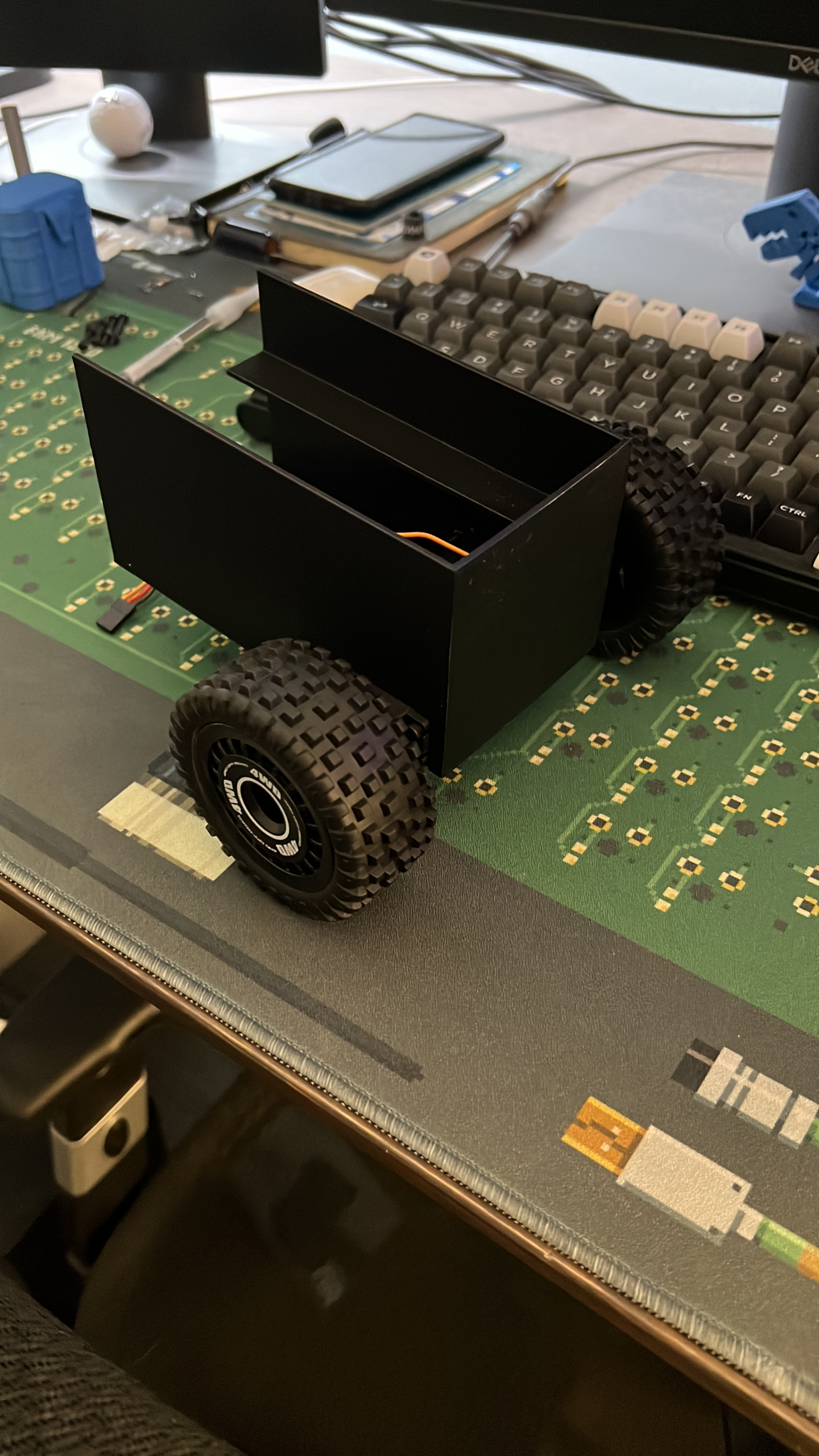
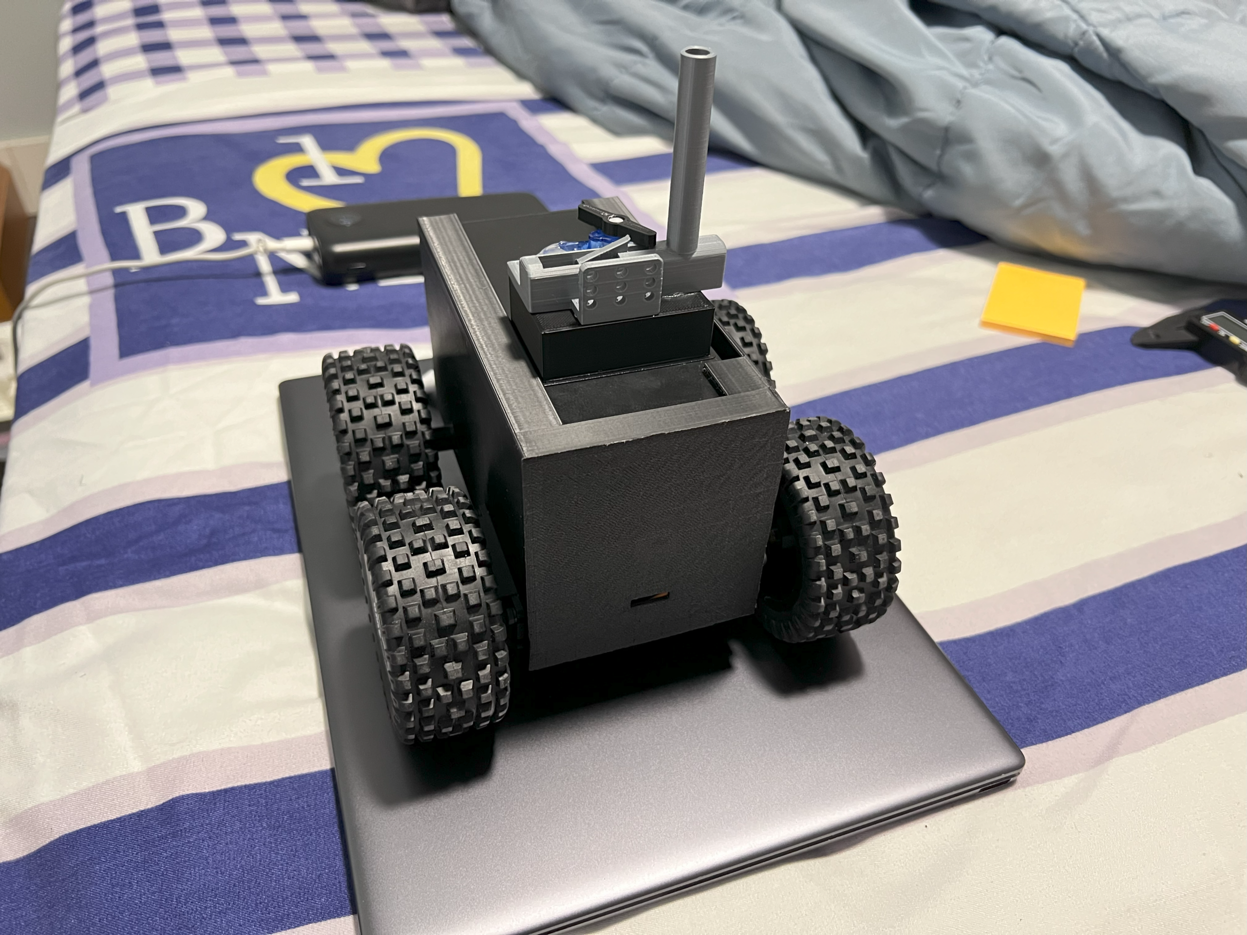
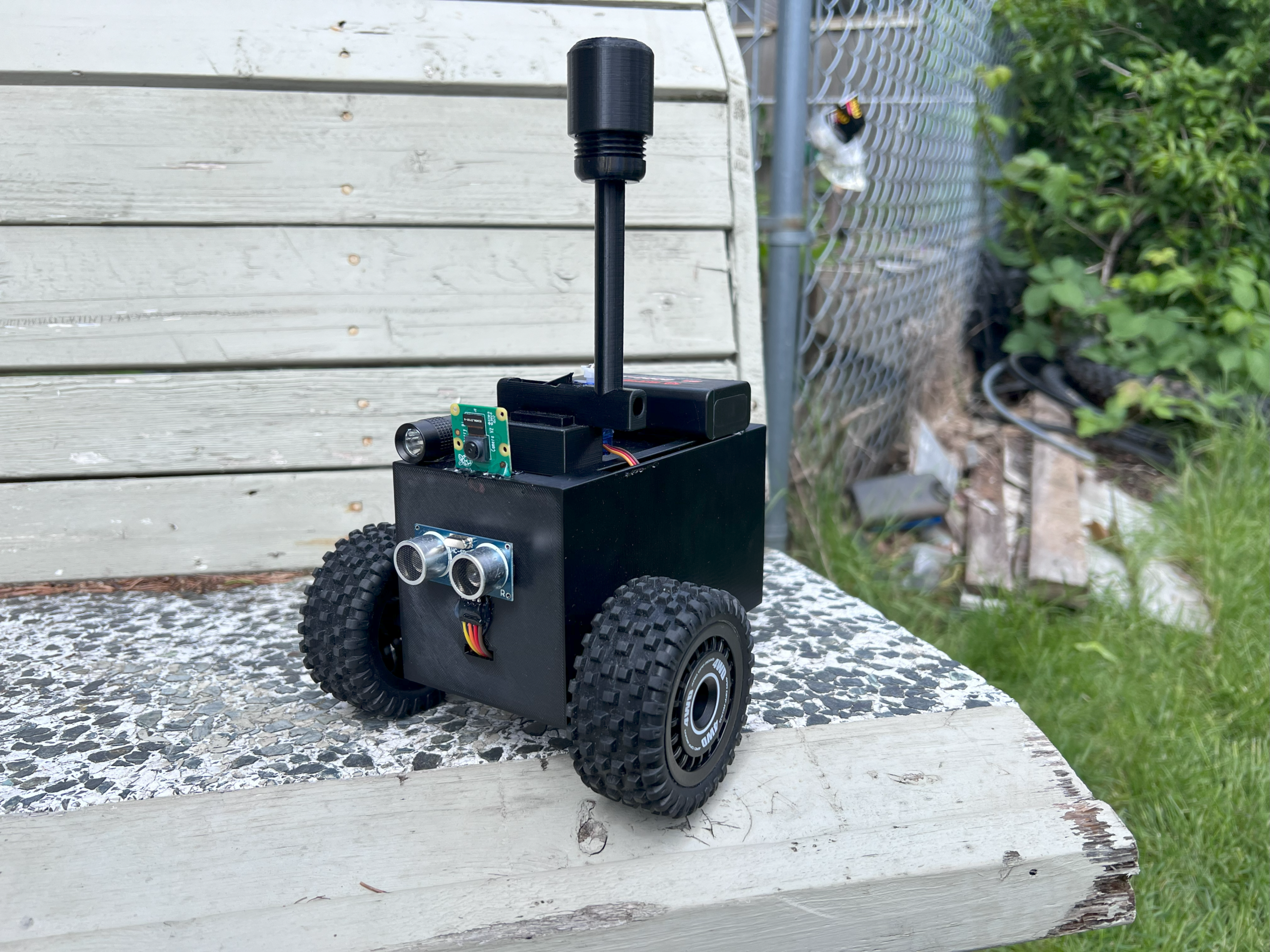
Prototype Images
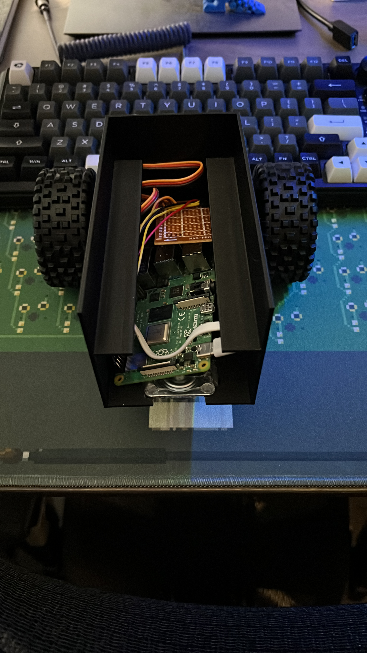
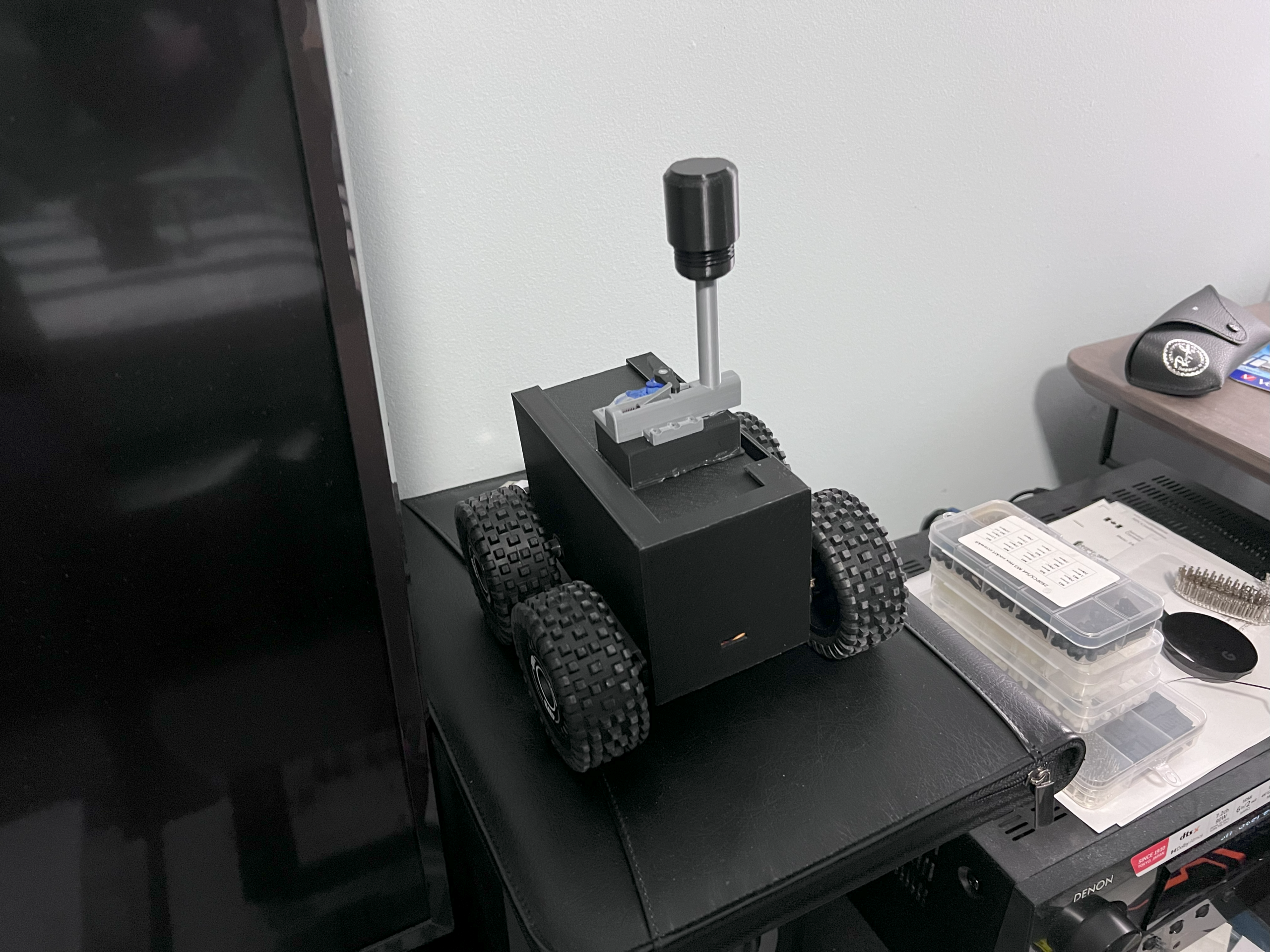
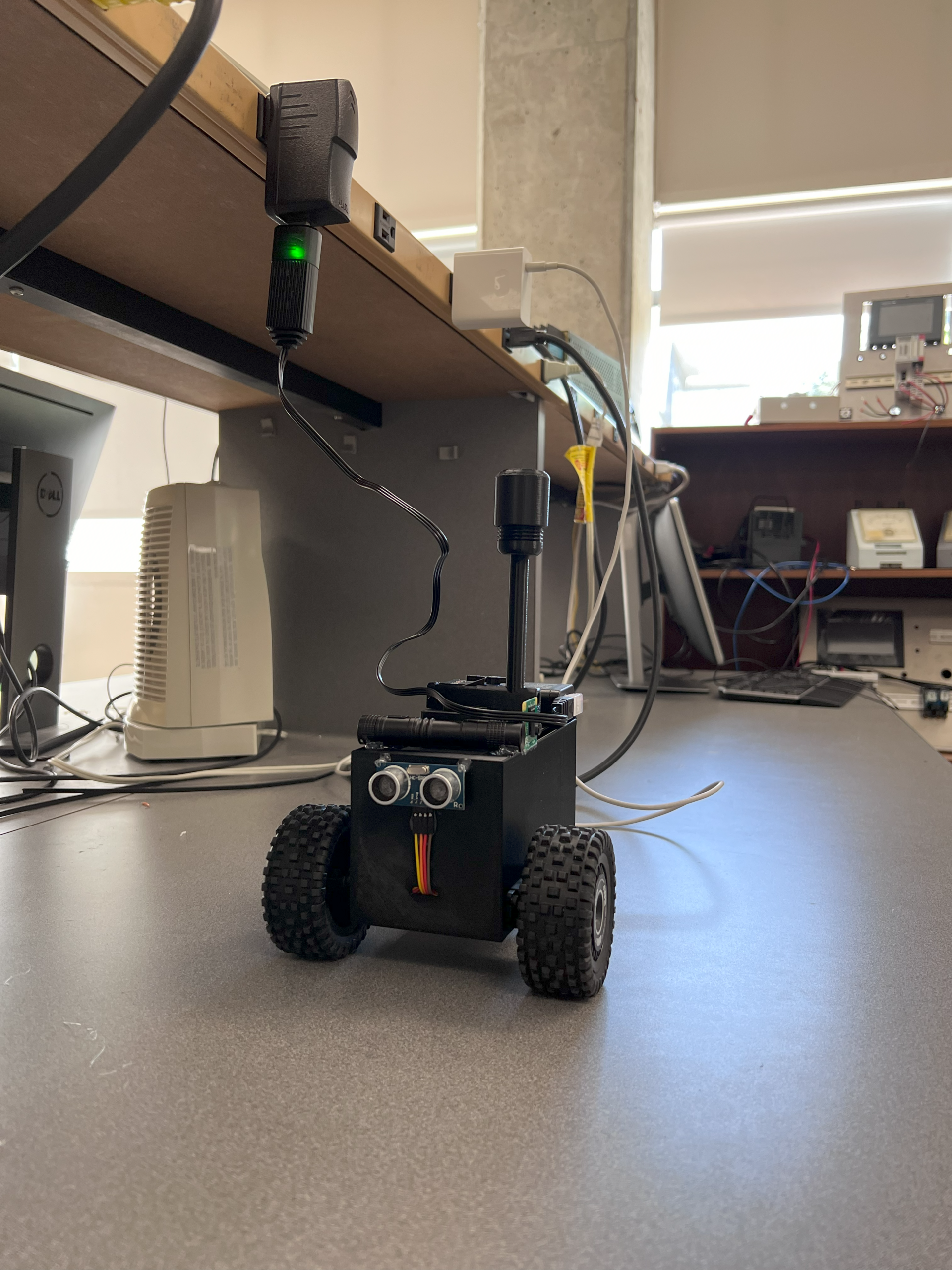
Final Build
I enjoyed working on this project and it was a great learning experience. One thing I would do differently if I had to redo this project would be to use DC motors and a motor driver board instead of servos for driving. The servos need a PWM signal to control their speed, balancing the left and right servos to spin at a similar speed was time-consuming. And as the battery voltage changes, the calibration wears off and has to be redone. These motors are also quite slow.
That being said, I am proud of the robot rover we built in 4 weeks.